The Basics of Refining
The first step in refining is to heat the crude oil to about 350 degrees Celsius and vapourize it in a tall unpressurized tower, called an atmospheric distillation tower. As the vapour rises through the tower it cools and components condense out at different levels based on their boiling points.
Components with the lowest boiling points, such as propane, butane and light naphtha, are removed from the top of the tower as vapours and condensed. Heavy naphtha liquid is taken from the upper section of the tower and further processed downstream into gasoline. Distillates are removed from the middle section of the tower. These are sent to finishing operations for use as kerosene, diesel, and jet fuel.
The remaining liquid residue in the bottom of the atmospheric tower is sent to a second distillation tower that operates under a vacuum. This tower is able to vaporize some of the residue into components as described above. In the case of heavy oil, like oil sands petroleum, the residue from vacuum distillation is still substantial (200,000 barrels per day in KC’s case). The residue, or residuum, is normally sent to coking units to remove much of the carbon.
Following distillation, subsequent refinery processes are used to alter the molecular structures of the components to create more desirable products. One of these processes is called cracking. The basic types of cracking are thermal cracking, catalytic cracking and hydro-cracking.
Thermal cracking, which includes coking, is used to obtain naphtha liquid and various middle distillate fractions. The residue from coking is almost a pure carbon solid called petroleum coke.
Catalytic cracking uses heat and catalysts to rearrange molecular structures, converting heavy feedstocks into lighter fractions such as kerosene, gasoline, LPG, and heating oil.
Hydrocracking is a two-stage process combining catalytic cracking and hydrogenation, wherein distillate fractions are cracked in the presence of hydrogen and special catalysts to produce more desirable products. Hydrocracking has an advantage over catalytic cracking in that high-sulphur feedstocks can be processed without previous desulphurization.
Reforming processes convert low-octane heavy naphthas into hydrocarbons for petrochemical feedstocks and high-octane gasoline components by molecular rearrangement or dehydrogenation. Hydrogen, a significant by-product, is separated for recycling and use in other processes.
High-purity hydrogen (95 to 99%) is needed for hydrodesulphurization, hydrogenation, hydrocracking and petrochemical processes. If not enough hydrogen is produced as by-products of refinery processes to meet the total refinery demand, the manufacture of additional hydrogen is required. It is typically produced from natural gas.
Hydrotreating is used to remove contaminants, including nitrogen, sulphur, metals and unsaturated hydrocarbons, from liquid petroleum fractions such as straight-run gasoline. Hydrotreating is similar to hydrocracking in that both the hydrogen and the catalyst are used to enrich the hydrogen content of the feedstock. Hydrotreating processes differ depending upon the feedstocks and catalysts. Hydrodesulphurization removes sulphur from kerosene, reduces aromatics and gum-forming characteristics, and saturates any olefins. Hydro-reforming is a dehydrogenation process used to recover excess hydrogen and produce high-octane gasoline. Hydrotreated products are blended or used as catalytic reforming feedstock.
Kitimat Refinery Process Description
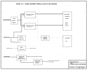
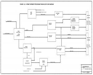
The proposed refinery will have a capacity to process 400,000 barrels per day of bitumen feed. The capacity will be split between two identical processing lines, or trains, with shared utility and offsite facilities. Figure 8.2.1 shows an overall block flow diagram of the refinery with major inputs and blocks identified. Figure 8.2.2 shows the block flow diagram for each of the two processing trains. There are two possible variations to the construction schedule: 1) The project may be phased for construction efficiency purposes with the second train of units projected to start up two years after the first; and 2) The Fischer Tropsch portion of the refinery may be started up while the remainder of the refinery is being built, allowing the early production of diesel from natural gas.
The crude oil will be received by rail and stored in tanks common to the two processing trains. The refined or finished product blending and storage and the sulphur by-product handling will also be common to the two trains. The sulphur recovery facilities include Claus Reaction Units with Tail Gas Recovery and Cleanup units for a recovery of over 99.9%.
The processing trains require hydrogen which will be produced by steam- methane reforming (SMR) using natural gas as a feedstock. Following the processing in the trains the Fischer-Tropsch process will utilize hydrogen produced by additional SMR units. Natural gas will also be used as process fuel. In total, approximately 900 million cubic feet per day of natural gas will be required.
All 420 MW of electrical power required by the refinery will be produced using the steam generated as a by-product from the hydrogen production units. Separate boilers will be provided for facility start-up and for backup operation.
The refinery requires 250,000 barrels of water per day for steam generation, process uses and for cooling water. One half of this will be generated as a by-product from the FT and hydrogen production units. The other half of the water will be taken from wells drilled on the refinery site, and treated for use. Water will be recovered and reused to the maximum extent possible. There will be little or no waste water.
The block flow diagram of each of the Processing Trains is shown in Figure 8.2.2 where the major process streams are shown. This sequence is typical of processing of very heavy crude oils except that coking units are replaced with the FT process. Also, unlike many refineries in North America which use catalytic cracking technology, the refinery will utilize hydro cracking technology to increase the yield of liquid products and reduce emissions.
The first major process step in the refinery is to heat the bitumen up in a Crude Distillation Unit. The naphtha and distillate fractions of the bitumen will be recovered and sent to the Naphtha Hydro-Desulphurization (HDS) Unit and Distillate HDS Unit respectively.
The residuum from the Crude Distillation Unit is then processed in a Vacuum Distillation Unit where Gas Oils (materials in the lubricating oil boiling range) are recovered and sent to the Hydrocracker Unit.
The residuum from the Vacuum Distillation Unit is processed in a Solvent De-asphalting Unit (SDU) where it is mixed with a light paraffinic solvent (such as propane or butane) which extracts the heavy asphaltene materials. The De-asphalted oil (DAO) is fed to the Hydrocracker.
The heavy asphaltene material from the SDU is fed to a Partial Oxidation Gasification Unit where it is burned in an oxygen stream to produce a product gas of primarily hydrogen and carbon monoxide.
The hydrogen and carbon monoxide are then mixed with hydrogen-rich gas from an SMR unit and sent to a Fischer Tropsch Gas-to-Liquids Unit that produces naphtha and gas oil products. Carbon dioxide from the FT process block is recycled to the SMR to improve product yield and reduce emissions.
Heavy hydrocarbon gas oils from the above various processing units are converted into lighter hydrocarbons in a Hydrocracker, which breaks chemical bonds by adding hydrogen in the presence of a catalyst. The Kitimat hydrocracker will convert all of the gas oils into diesel, kerosene and naphtha. The unit will have a number of large reactor vessels containing catalyst that operate at about 2500 psig.
Light hydrocarbon streams from the process units (containing methane, ethane, propane and butanes) are processed in a Light Ends Unit. The lightest components are then used for refinery fuel, the propane is recovered for local sales, and the mixed butane stream is sent to an Iso-Octane Unit to produce a high octane gasoline blending component.
The naphtha processing facilities include the Naphtha HDS Unit, a combination Benzene Saturation/Isomerization Unit and a heavy Naphtha Reforming Unit. These facilities produce the components required to blend gasoline products.
Other product blending facilities enable the production and segregation of various products destined for market. The products will be exported via a marine terminal on the Douglas Channel. Projected volumes include 320,000 barrels per day of diesel fuel, 110,000 barrels per day of gasoline and 60,000 barrels per day of jet fuel.
If it is not used in local petrochemical applications, sulphur recovered from the oil will likely be transported by rail to Prince Rupert where it will be exported. The projected amount of sulphur is 2,400 tons per day (24 rail cars).
The Marine Terminal will be somewhat similar in design to that of the proposed Northern Gateway. The main difference between the two proposals is that prior to shipping the Proponent would store refined fuels at the refinery site to avoid spills into the sea caused by large earthquakes, whereas Northern Gateway wanted to store dilbit at the Marine Terminal site.


